2 Symbols, Fundamental Rules, and Comparison Operators
- 2.1 Start Event e Timer Start Event
- 2.2 End Event
- 2.3 Intermediate / Boundary Event Timer
- 2.4 Exclusive e Parallel Gateway
- 2.5 Conditional Task and Action Task
- 2.6 CONNECTORS (CONNECTIONG OBJECT)
- 2.7 Basic rules
- 2.8 Comparison Operators: Description and Use in Conditional Tasks.
- 2.9 Comparison operators: Rules of use in initial condition tasks
- 2.10 Configuration Section “When to run the check” in the Initial Condition Task.
- 2.11 Configuration Section “When to run the check” in Conditional Tasks
- 2.12 Managing Visibility Permissions in Processes
- 2.13 Process Manager: Versioning Management
2.1 Start Event e Timer Start Event
START EVENT
It represents the unique point from which each individual process begins. This means that only one can be present in each process, as the flow starts from a single point.
Note: It must always be followed by a control task, as this represents the task where the conditions are entered that, if met, will trigger the process.

Timer Start Event

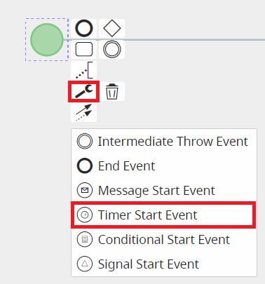
A particular type of timer is the "Timer Start Event", which is applied to the Start Event to allow a specific process to begin at a predefined time interval.
It can be selected in diagram editing mode by first clicking on the Start Event, then on the wrench icon that appears among the selectable options, and finally choosing the "Timer Start Event" option.
Note: This type of start event must be followed by an action task, as it only allows actions to be executed.
Other types of Start Events are currently not implemented.
IMPORTANT NOTE: As of version 24.08, they have been completely removed.
2.2 End Event
END EVENT
It represents the endpoint of a process.
Unlike the Start Event, it can be used more than once within a single process, since the flow may end at multiple points.

2.3 Intermediate / Boundary Event Timer
INTERMEDIATE/BOUNDARY EVENT TIMER
It represents an element widely used for managing the timing of task and process execution.

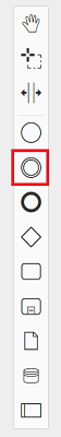
It can be quickly selected from the menu on the left while in diagram editing mode.
There are two groups of timers, which differ based on the actions to be performed and the tasks/elements involved:
1) Intermediate Event Timer
2) Boundary Event Timer
1) INTERMEDIATE EVENT TIMER
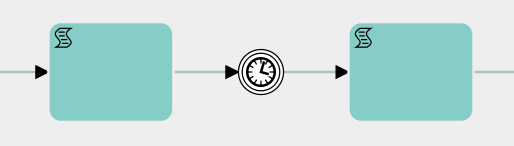
The first group consists of various types of "Intermediate Events" and is used between two tasks/elements.
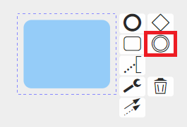
They can be selected in diagram editing mode by first clicking on the task or element from which the flow should then continue to the timer, and then clicking on the icon showing two circles, called "Intermediate/Boundary Event Timer."
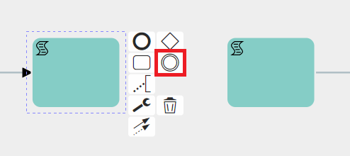
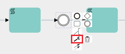
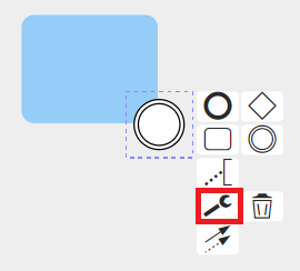
At this point, you need to select the timer just mentioned, click on the wrench icon, and then choose one of the available options.
Timer Intermediate Catch Event
This is a type of timer used to wait for a specific period of time before moving on to the next task/element.
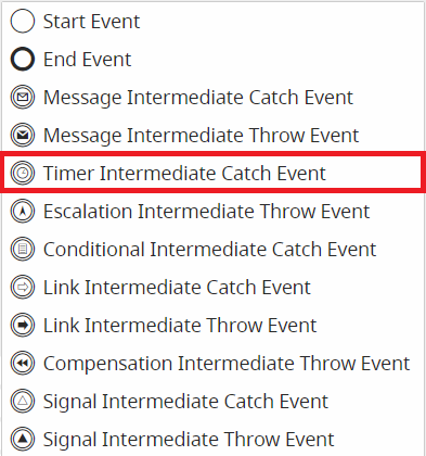
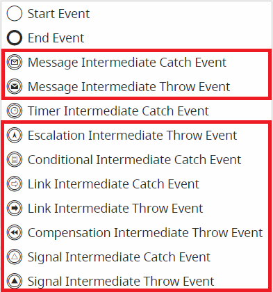
The other selectable types of Intermediate Events are currently not implemented.
IMPORTANT NOTE: As of version 24.08, they have been completely removed.
During the configuration phase, by clicking on the Timer Intermediate Catch Event symbol, a dedicated interface opens where you can enter the waiting time and the date to be used as a reference.
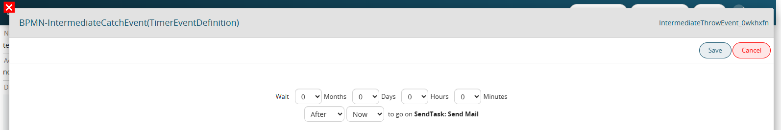
Inside the first picklist starting from the left, it is possible to indicate whether to wait for the indicated timing BEFORE or AFTER the reference date.
Instead, in the next picklist, three values are made available:
- Now -> as the reference date it will take the date-time (timestamp) of the precise moment in which the process is positioned on the timer.
- Date -> allows you to insert a static date-time
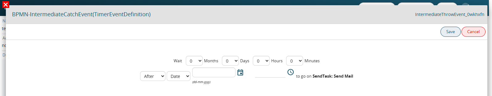
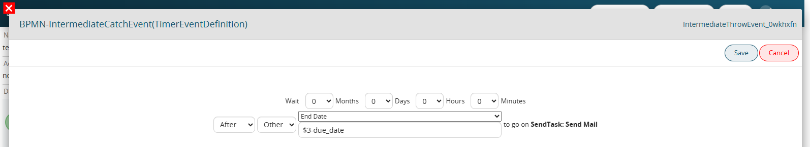
Other -> allows you to insert dynamic values, therefore taken from the date fields of the modules involved in the process.
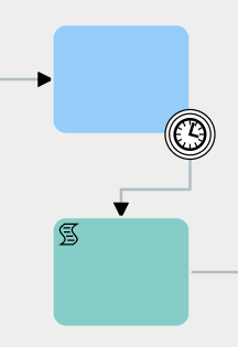
2) BOUNDARY EVENT TIMER
The second group consists of various types of Boundary Events, which are used on control tasks and are triggered when a task remains idle for a specific period of time.
They can be selected in diagram editing mode by first clicking on the task or element from which the flow should then continue to the timer, and then clicking on the icon showing two circles, called "Intermediate/Boundary Event."
At this point, you need to select the timer just mentioned and drag it onto one of the edges of the relevant control task.

(Note: If you simply click on the icon, an “Intermediate Event” will be created and linked to the task with an arrow. If you want to use that timer as a Boundary Event, you just need to delete the arrow and place the timer directly on the relevant task.)
Once this is done, you need to select the timer, click on the wrench icon, and then choose one of the available options.

Timer Boundary Event
Allows the execution of the tasks/elements connected to the timer based on how long the process remains idle on the control task where the timer is placed.


The time interval is predefined during the timer’s configuration.
They can only be used on control tasks.
The other types of selectable Boundary Events are not currently implemented.
IMPORTANT NOTE: As of version 24.08, they have been completely removed.
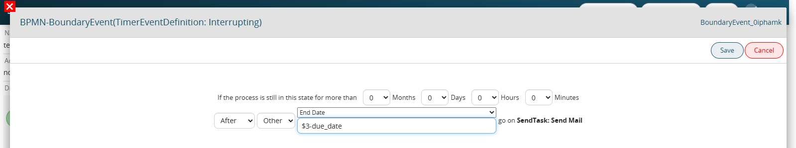
During configuration, clicking on the Timer Boundary Event icon opens the dedicated interface where you can enter the waiting times.
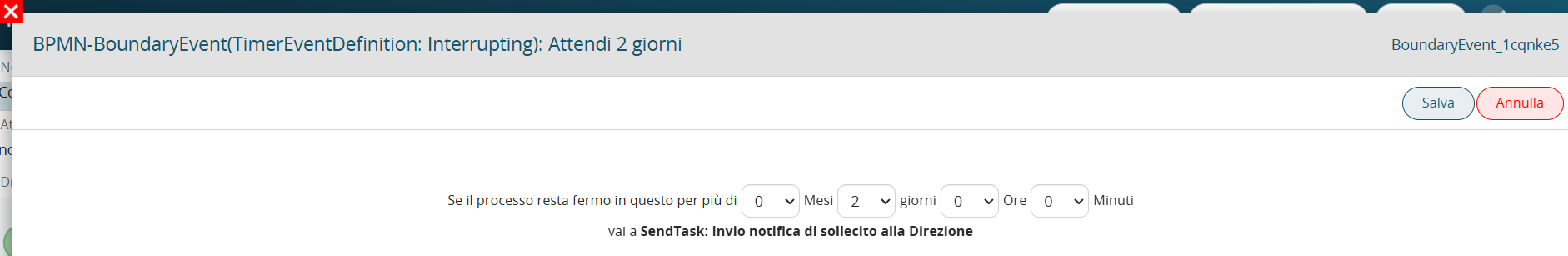
As of version 25.02, it is possible to specify a reference date on which to base the waiting times.
The configuration of this section is the same as for the intermediate timer, so in the first picklist from the left, you can indicate whether to wait the specified amount of time BEFORE or AFTER the reference date.
In the next picklist, three values are available:
- Now → the reference date will be the date-time (timestamp) of the exact moment when the process reaches the timer.
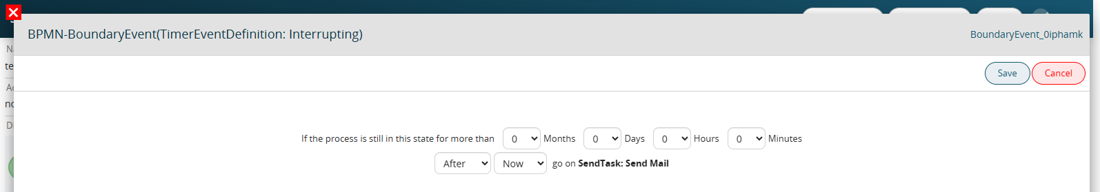
- Date → allows you to enter a static date-time value.
- Other -> allows you to insert dynamic values, therefore taken from the date fields of the modules involved in the process.
2.4 Exclusive e Parallel Gateway
Exclusive Gateway
Allows the process flow to split into multiple different branches.
It must be preceded by a control task in which the parameters are defined to determine which branch of the Gateway will be followed.

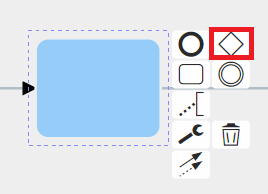
To use it, in diagram editing mode, you need to click on the control task and then select the diamond-shaped symbol called “Gateway.”
Here is an example of an applied Exclusive Gateway.
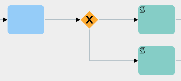
Like all other symbols, it can also be selected from the quick menu on the right.
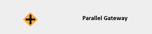
Parallel Gateway
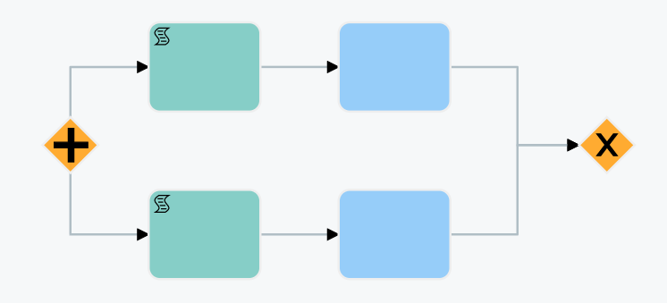
It performs the same function as the Exclusive Gateway, with the only difference being that all branches are executed in parallel. At the end of the branches, an Exclusive Gateway must be present to act as the closing Gateway for the parallel flow. Before the closing Gateway, as many control tasks must be configured as there are branches involved.
This type of structure allows you to choose whether to proceed with the flow upon completion of certain specific branches of the Gateway or wait for all existing branches to be completed.
Note:
- Parallel Gateways cannot be used within other Parallel Gateways. - Multiple Parallel Gateways cannot share a single closing Exclusive Gateway.
To use it, while in diagram editing mode, you need to click on the task and then select the diamond-shaped symbol called “Gateway.”
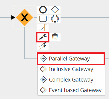
Here is an example of an applied Parallel Gateway.
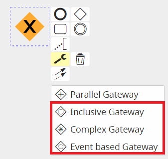
The types of Gateways listed below are not currently implemented.
NOTE: As of version 24.08, they have been completely removed.
2.5 Conditional Task and Action Task
CONDITIONAL TASK
Represents the element used to perform creation and control actions within the flow of a process.

ACTION TASK
To define the type of task, Vtenext provides symbols that can be used to indicate the action performed by each task.
These symbols can be selected during the diagram editing mode by pressing on the task and then later on the wrench that appears among the various selectable options.
![]()
![]()
It is important to point out that these symbols do not go to affect the behavior of individual tasks, as their purpose is simply to show an initial visual reference that can facilitate the interpretation of individual tasks. Thus, it will be at the user's discretion to select the symbol most appropriate to the action performed by any given task.
Once selected, each symbol will be placed at the top left of the task and will be visible during process configuration.
Below is an example for each selectable type:
Script Task
![]()
It is advisable to use it to indicate the creation and updating of tasks.
Send Task
![]()
It is advisable to use it to indicate the sending of emails and notifications.
Receive Task
![]()
There is no particular recommended use.
User Task
![]()
It is advisable to use it to indicate a task in charge of the user.
Manual Task
![]()
It is advisable to use it to indicate a task in charge of the user (process helper).
Business Rule Task
![]()
There is no particular recommended use.
Service Task
![]()
It is advisable to use it to indicate the calling of external Webservices or SDKs.
On the other hand, the only two symbols that allow a given action to take place and thus condition the behavior of a given task are the “Call Activity” and the “Sub Process.”
![]()
Call Activity
This symbol allows you to perform an action that is not currently implemented.
PLEASE NOTE: As of version 24.08 it has been completely removed.
Sub Process (collapsed)
This symbol allows you to call and use a sub process.
2.6 CONNECTORS (CONNECTIONG OBJECT)
CONNECTORS (CONNECTIONG OBJECT)
If the flow elements (events, activities or branches) in a process are “what actually happens,” they must be logically connected to each other. This is what connectors are for.
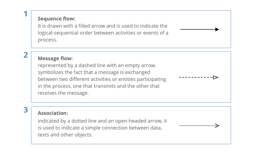
Connectors must always have flow direction.
2.7 Basic rules
1 - Upon process creation, the system automatically inserts a Start Event (see Chapter 2.1 for details), which is the element that represents the unique point from which each individual process begins.
There can only be one in each individual process, since, the flow starts from a single point. (Figure 1 and 2)
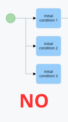
Figure 1
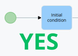
Figure 2
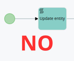
Figure 3
Figure 4
The same logic applies to the Timer Start Event, the only difference being that only a task of any type except Conditional Task can be attached. (Figure 5 and 6)
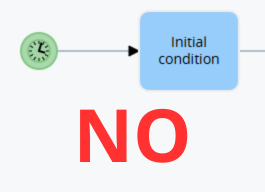
Figure 5
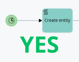
Figure 6
3 - Before an Exclusive Gateway there must always be a Conditional Task that allows you to define sets of conditions on the basis of which the process will split into multiple branches. (Figure 7 and 8)
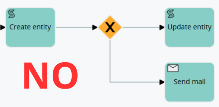
Figure 7
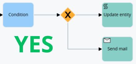
Figure 8
2.8 Comparison Operators: Description and Use in Conditional Tasks.
The system provides several comparison operators that can be used within Conditional Tasks, which are the types of tasks that allow you to perform checks on the fields of the dynamic forms/forms involved within the process.
WARNING! -> the system is “Case Sensitive,” so the same values with different upper or lower case are treated as if they were different.
Example: “VTENEXT” and “vtenext” are seen by the system as different values.
- “equals” -> allows checking whether the contents of a field are equal to a static value specified within the condition. (Figure 1)
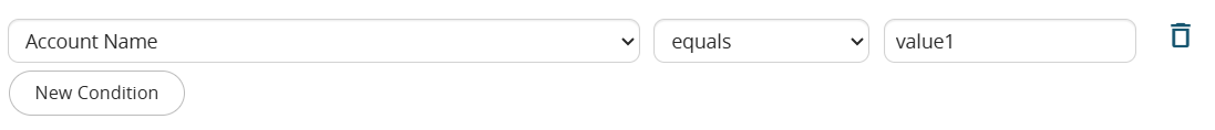
Figure 1
PLEASE NOTE: the system does not allow you to compare multiple values at the same time on the same row, so in case you need to perform a multiple check you will have to create separate conditions (Figure 2 and 3)

Figure 2
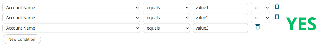
Figure 3
- “different”->allows to check whether the contents of a field are NOT equal to a static value specified within the condition. (Figure 4)

Figure 4
- “contains” -> allows checking whether the static value specified within the condition is present within a field, regardless of where it is located. (Figure 5)
Taking the example given in Figure 5 as a reference, in case we have a company named “demo_vtenext”, the condition will be verified, since, this tringa contains “vte”.

Figure 5
In contrast to the “equal” operator, the system allows multiple values to be compared simultaneously on the same row (Figure 6)

Figure 6
- “does not contain” -> allows checking whether the static value specified within the condition is NOT present within a field, regardless of where it is located. (Figure 7)

Figure 7
As with the “contains” operator, multiple values can be compared at the same time on the same row (which should be entered separated with a comma).
- “starts for” -> allows you to check whether the contents of a field begin with the static value specified within the condition. (Figure 8)

Figure 8
PLEASE NOTE: the system does not allow you to compare multiple values at the same time on the same row, so in case you need to perform a multiple check you will have to create separate conditions (take Figure 2 and 3 as reference)
- “ends with” ->allows you to check whether the contents of a field ends with the static value specified within the condition. (Figure 9)
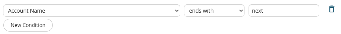
Figure 9
PLEASE NOTE: the system does not allow you to compare multiple values at the same time on the same row, so in case you need to perform a multiple check you will have to create separate conditions (take Figure 2 and 3 as reference)
- “has changed to” -> allows you to check whether the contents of the field has precisely changed to the value specified within the condition (Figure 10)
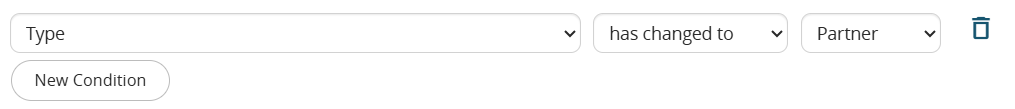
Figure 10
For all those types of fields that might have an undefined value (text, number, date, related to, etc.), by combining the “has changed to” operator with the “different” operator, it is possible to configure a condition to capture a change in the content of a field to a consistent value that you are not aware of. (Figure 11)
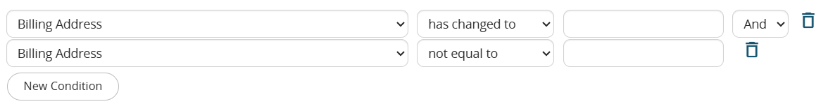
Figure 11
The example shown in Figure 11 translates to the following statement: "The expected closing date has changed to a value I cannot define, but at the same time, that value is not empty, so it must be a valid value."
Starting with version 26.07, the logic for selecting values in Picklist fields has been improved.
Specifically, selectable values are displayed within a multi-select combo box, allowing multiple values to be selected simultaneously.
Additionally, an "Any Value" option has been added, making it easy to include all existing picklist values without having to manually add any new values introduced in the future. (Figure 12)
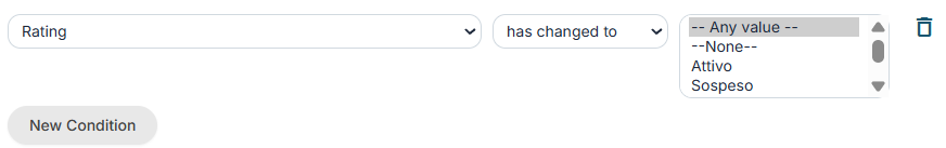
Figure 12
- “has changed from” -> allows you to check whether the contents of the field has changed from one value to another, both of which are specified within the condition (Figure 13)
The first slot should specify the value that the field had before the change, while the second slot should specify the new value that was entered.

Figure 13
- “greater than” -> allows you to check whether the content of a number/currency field present is greater than an entered static value specified within the condition. (Figure 14)

Figure 14
- “greater than or equal” -> allows checking whether the content of a number/currency field present is greater than or equal to an entered static value specified within the condition. (Figure 15)

Figure 15
- “less than” -> allows you to check whether the content of a number/currency field present is less than an entered static value specified within the condition. (Figure 16)

Figure 16
- “less than or equal” -> allows checking whether the content of a number/currency field present is less than or equal to an entered static value specified within the condition. (Figure 17)

Figure 17
- "in" -> Starting with version 26.07, this operator is available; it allows you to check whether the value in a picklist field matches at least one of the values specified within the condition. (Figure 18)
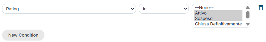
Figure 18
- "not in" -> Starting with version 26.07, this operator is available; it allows you to verify whether the value in a picklist field does NOT match any of the values specified within the condition. (Figure 19)
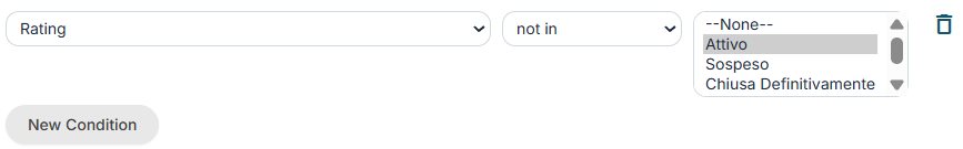
Figure 19
2.9 Comparison operators: Rules of use in initial condition tasks
Some comparison operators should be used carefully within the “Initial Condition” Tasks, i.e., those Conditional Tasks directly associated with the Start Event within which conditions are defined that allow the process to be triggered or not. (Figures 1 and 2).
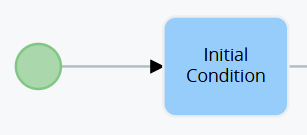
Figure 1
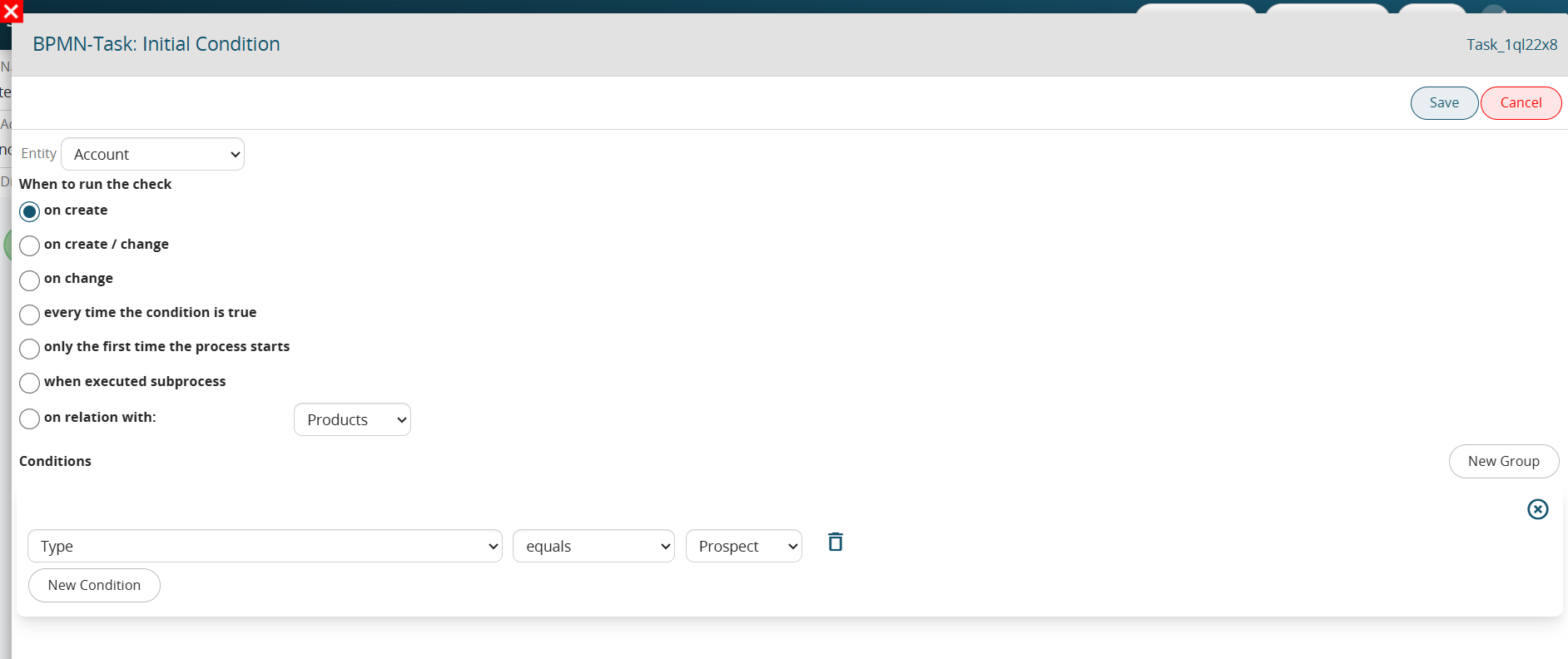
Figure 2 (click on the image for a higher graphic resolution)
Specifically, in the case where the “edit” phase is involved in the condition (thus selecting one of the following: “upon editing” , “upon creation and modification”, “whenever the condition turns out to be true”), the comparison operators “equal”, “different”, “contains”, “does not contain”, “starts with”, “ends with”, “greater than”, “greater than or equal”, “less than”, “less than or equal” cannot be used individually, because, there is a risk of creating loops, i.e., the unwanted and uncontrolled departure of multiple instances of the same process.
This is because, the comparison operators just mentioned simply look at whether the condition is verified or not, without taking into consideration in which specific save that condition first occurred.
To better understand how they work, Figure 3 shows an example of an Initial Condition Task that is NOT properly configured.
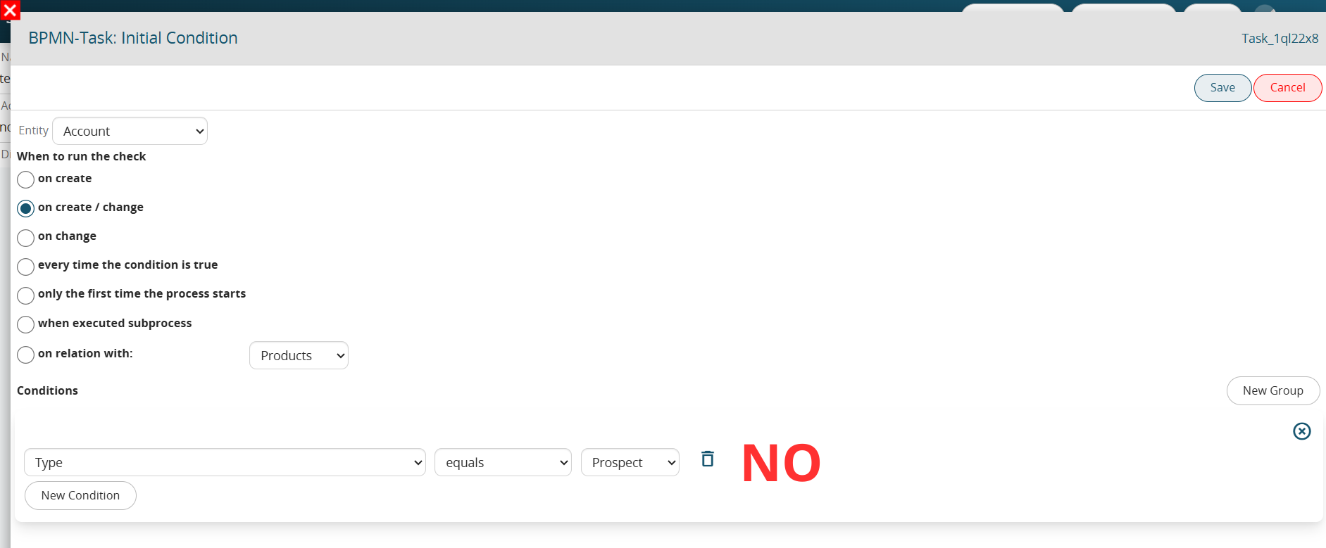
Figure 3 (click on image for higher graphic resolution).
The condition “Type” = “Potential” simply tests whether that field possesses that specific value.
By then setting this condition individually and involving editing (in this case by selecting “upon creation and editing”), the process will not only be triggered on the save where the “Type” is set to “Potential” but also on subsequent saves as long as the “Type” field retains that specific value.
Precisely to overcome this issue, the system provides the “has changed to” and “has changed from” comparison operators that allow the process to trigger only in the save in which the setting of that specific value occurred.
So, by configuring the process as shown in Figure 4, the process will only trigger on the save in which the value in “Potential” is set.
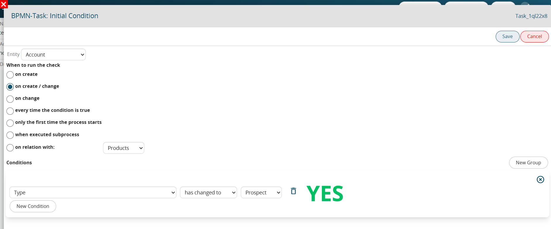
Figure 4 (click on image for higher graphic resolution)
2.10 Configuration Section “When to run the check” in the Initial Condition Task.
Within the “Initial Condition” Tasks, i.e., those Conditional Tasks directly associated with the Start Event within which the conditions that allow the process to be triggered or not are defined, the “When to Run Control” section is presented with the following values:
- “at creation” -> the process will trigger only after the creation of a record (instance of a form)
- “upon creation and modification” -> the process will trigger after the creation or modification of a record (instance of a form), so in fact in all situations currently handled in the processes.
PLEASE NOTE: deletion of a record is a situation not handled in processes
- “upon modification” -> the process will be triggered only after the modification of a record (instance of a module)
- “whenever condition is true” -> the process will be triggered upon occurrence of the conditions (always after saving) entered in the “Conditions” section.
Conditions can also be entered in the “Conditions” section for other values, so this item turns out to be for all intents and purposes analogous to the “upon creation and modification” item, this is because both creation and modification are involved.
- “only the first time the process is triggered” -> the process will trigger are the first time the condition entered in the “Conditions” section occurs.
Thereafter, the process can never trigger on that specific record (instance of a module) again, even if the conditions configured within it have occurred.
- “at subprocess launch” -> is used exclusively for subprocess configuration and allows the subprocess to be triggered the moment the callback task configured in the parent process is executed.
- “in relation with” -> allows the process to be triggered the moment a relation is established between two records (instance of a module) of two modules having an N - N relation
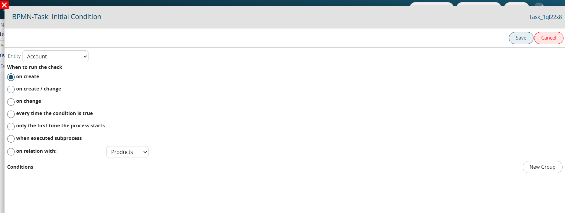
Figure 1 (click on image for higher graphic resolution)
2.11 Configuration Section “When to run the check” in Conditional Tasks
Within classic Conditional Tasks, i.e., those Tasks used to perform checks within the process, the “When to check” section is presented with the following values:
- “upon change” -> the process will wait for a change in the record (instance of a form) involved before checking the conditions configured within the Conditional Task, even if they should already be checked.
- “whenever condition is true” -> the process will immediately verify the conditions configured within the Conditional Task, then continue with the flow in case they should already be verified.
To better understand how it works, Figure 1 shows a process that, when an opportunity is created, performs a check on the Sales Stage and is divided into two different branches. (Figure 1)
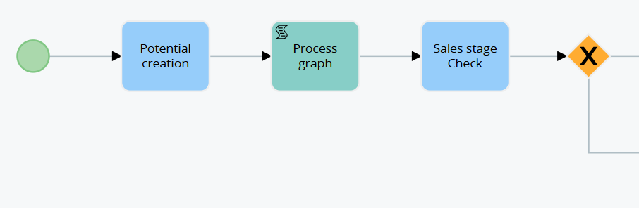
Figure 1
In the event that the Conditional Task “Checking Sales Stage” was set “upon modification,” even though the opportunity being created will have the “Sales Stage” = “Open” or “To be Analyzed,” the process will not consider the conditions verified.
This is because a post-creation save of the opportunity will be waited for before verifying the conditions configured within it. (Figure 2)
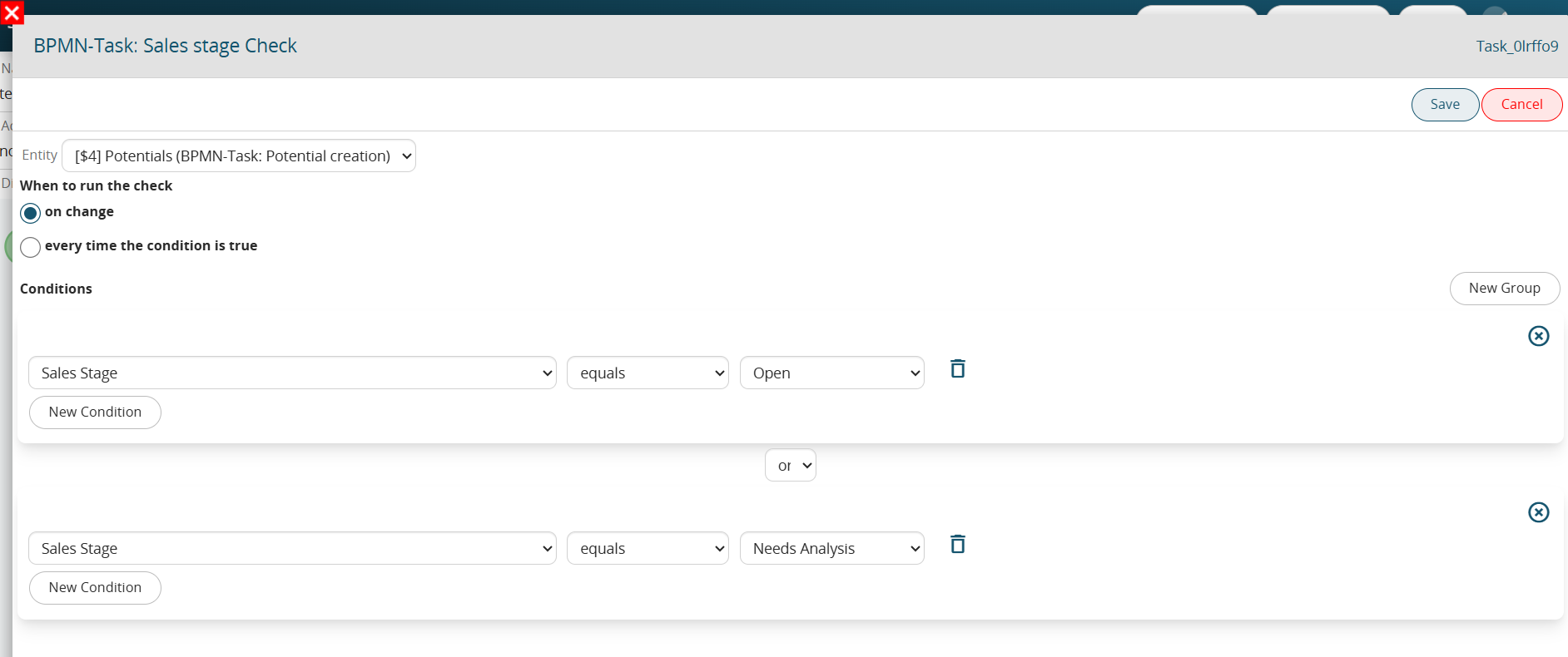
Figure 2
On the other hand, in the case where the Conditional Task “Checking Sales Stage” had been set “whenever condition is true,” if the opportunity being created will have the “Sales Stage” = “Open” or “To be Analyzed,” the system will perform a check in the immediate proceeding then in the first or second branch in case there are verified conditions. (Figure 3)
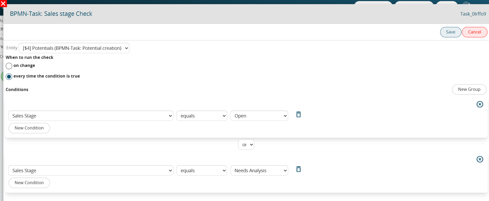
Figure 3
2.12 Managing Visibility Permissions in Processes
As with any other standard/custom module, to configure the visibility of the Processes module you must access the dedicated "Sharing Access" section located in Settings -> User Permissions -> Sharing Access. (Figure 1)
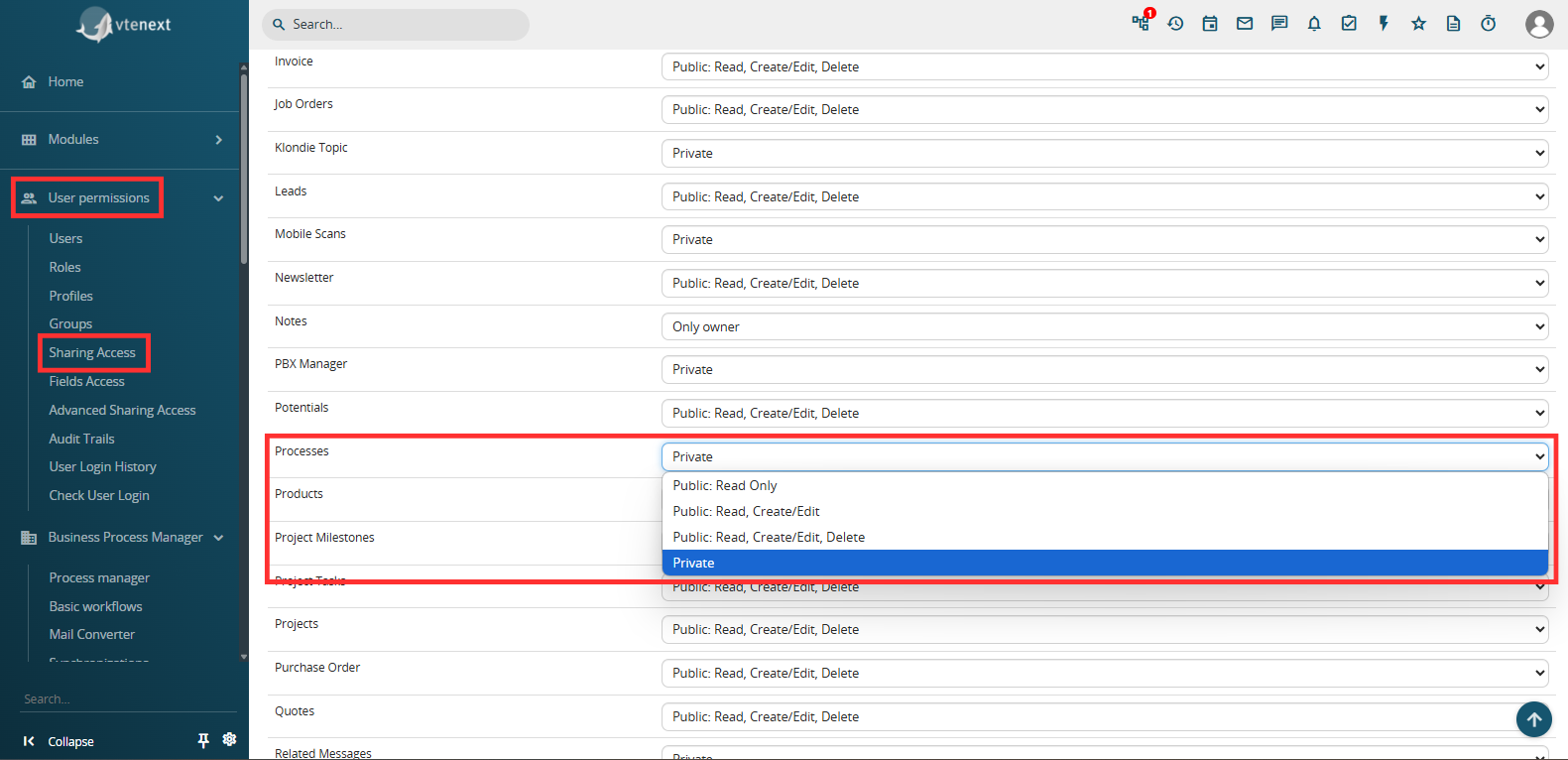
Figure 1
"Private" -> only the following users will be able to view the process:
- the user who triggered the process, that is, the user who made the change on the module record associated with the process by verifying the initial conditions defined.
Even if, in a specific phase of the flow, the process will be assigned to a different user, the user who triggered the process will still be able to see the process from start to finish with the respective graph.
EXAMPLE:
Considering the process shown in Figure 2 having in the EndEvent a Process Helper with assignee corresponding to the user "UserY" (Figure 3), in the case in which the process is triggered by "UserX", the latter will always be able to see the process even if in the EndEvent it is assigned to "UserY".
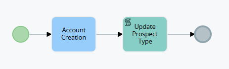
Figure 2
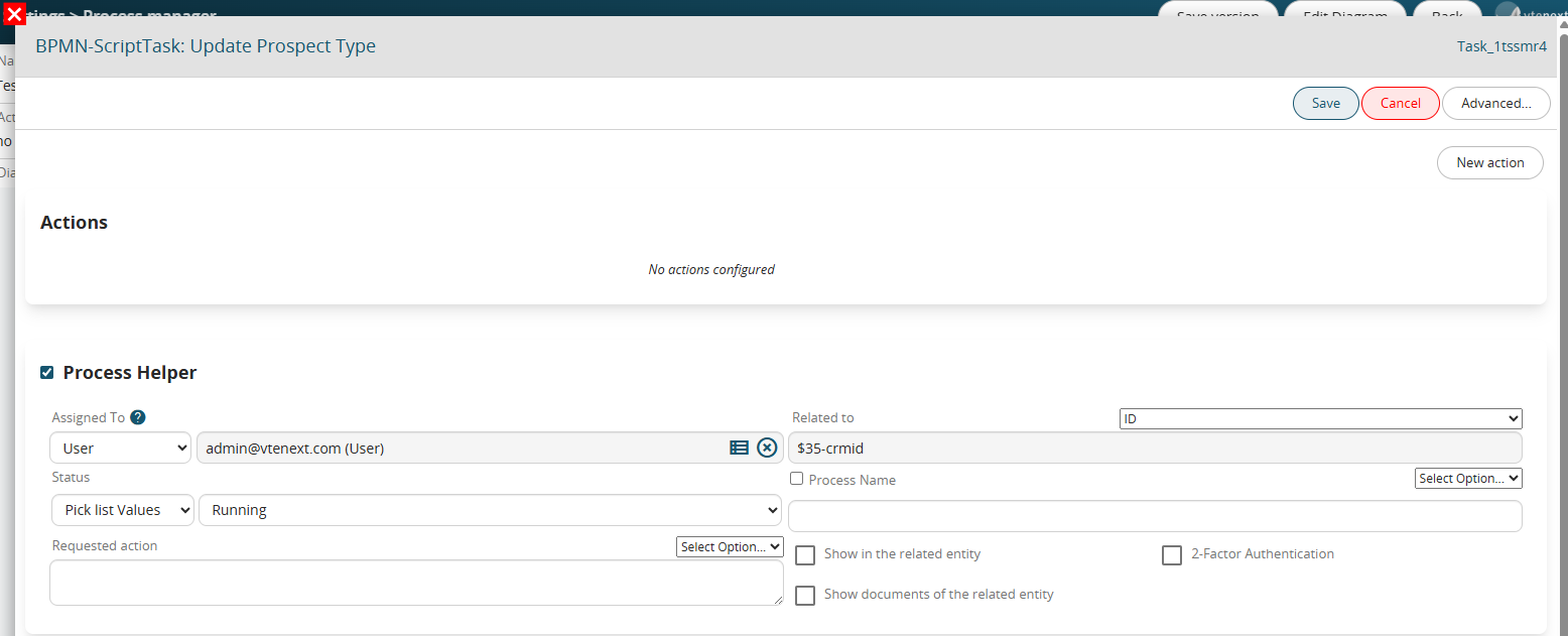
Figure 3
-all users with administrator permissions, that is, with the "Administrator" flag checked in their user preferences
-the user assigned to the Process Helper (and therefore the process) at that specific moment
-the user who performed an activity that allowed the process to continue with its flow, such as modifying a field on the form for which the process was waiting (via a Task)
EXAMPLE:
Considering the process shown in Figure 4, in the case in which the process is triggered by "UserX" and stops on the Task "Waiting for company modification", if the modification to the company is always performed by "UserX" and therefore "UserY" will not have any interaction with the process, in fact "UserY" will never be able to see the process.
If, on the other hand, the modification to the company is performed by "UserY", from that moment on he will be able to start seeing the process.
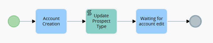
Figure 4
"Public: Read Only" -> all users in the system will be able to view active or terminated processes.
ATTENTION! -> this permission refers to the Processes module and not to the Dynamic Forms of the Process Helpers, so the latter will continue to refer to the Assigned to field of the Process helper and therefore be compilable only by the users or groups defined within it.
"Public: Read, Create/Modify" -> all users in the system will be able to view, create or modify active or terminated processes.
ATTENTION! -> this permission refers to the Processes module and not to the Dynamic Forms of the Process Helpers, so the latter will continue to refer to the Assigned to field of the Process helper and therefore be compilable only by the users or groups defined within it.
"Public: Read, Create/Modify, Delete" -> all users in the system will be able to view, create or modify and finally delete active or terminated processes.
ATTENTION! -> this permission refers to the Processes module and not to the Dynamic Forms of the Process Helpers, therefore the latter will continue to refer to the Assigned to field of the Process helper and therefore can be filled in only by the users or groups defined within it.
2.13 Process Manager: Versioning Management
Within each individual process configured in the system, there is a button called "Save Version" in the top left. (Figure 1)
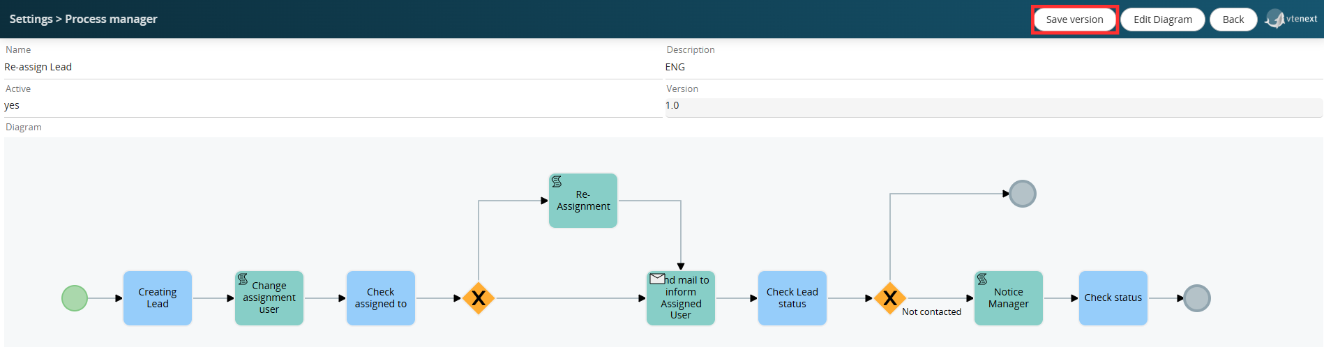
Figure 1
This allows you to force a new process version to be saved, ensuring its historicization in a dedicated DB table.
In simple terms, it simulates the "Export BPMN Process VTE" button, allowing you to save a copy of the current process configuration in a table other than the main table linked to the Process Manager section.
Furthermore, the value of the related "Version" field is also updated. (Figure 2)
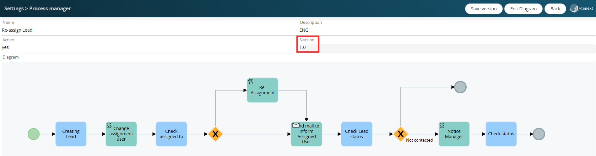
Figure 2
This type of operation is essential to ensure the ability to restore a previous version of the process in the event of configuration errors or other situations.
WARNING!: Deleting a process using the X button in the Process Manager section permanently deletes the process from all related tables in the database, including the aforementioned table.
Therefore, it is important to proceed with caution when using this function, as once the deletion is performed, there will be no way to restore the process and all pending instances associated with the records involved.
If you want to save a new version of a process with pending instances (in our case, some leads with the Lead Re-Assignment process active), the system will display the popup shown in Figure 3.
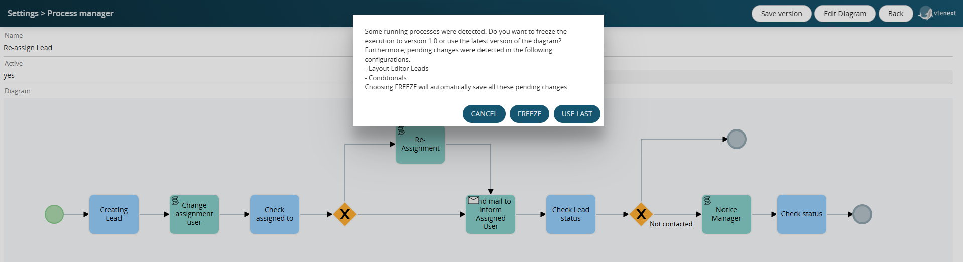
Figure 3
Furthermore, for completeness, all pending changes to Conditional Fields and Layout Editors for the modules in the system will also be displayed (even for modules not involved in the process, as the system performs a general check).
By clicking the FREEZE button, the system will automatically save the version of all pending changes indicated above and will NOT update the version of pending process instances on the identified records (in our case, maintaining version 1.0).
This feature is useful when you want to apply the new process version only to process instances starting in the future, or rather, from the time of the version update onward.
By clicking the USE LAST button, the system will update the version of pending process instances on the identified records (in our case, setting version 1.1).