6 Process Helper: Examples of Use
- 6.1 Example of using Process Helper to request internal user data
- 6.2 Example of using Process Helper to request external user data
- 6.3 Example of using Process Helper to request Business Portal user data
- 6.4 Example of using Process Helper to activate Process Graph
- 6.5 Example of Process Helper usage for internal process use
6.1 Example of using Process Helper to request internal user data
As anticipated in the introductory chapter, one of the most common uses of the process helper concerns the creation of customized forms that can be presented to internal users of the CRM in order to request and save information.
The blocks and fields that make up these forms are called "dynamic forms".
PREMISE: In order for a user to be able to view and fill out a dynamic form, he/she must have enabled the appropriate permissions on the profile side (Figure 1)
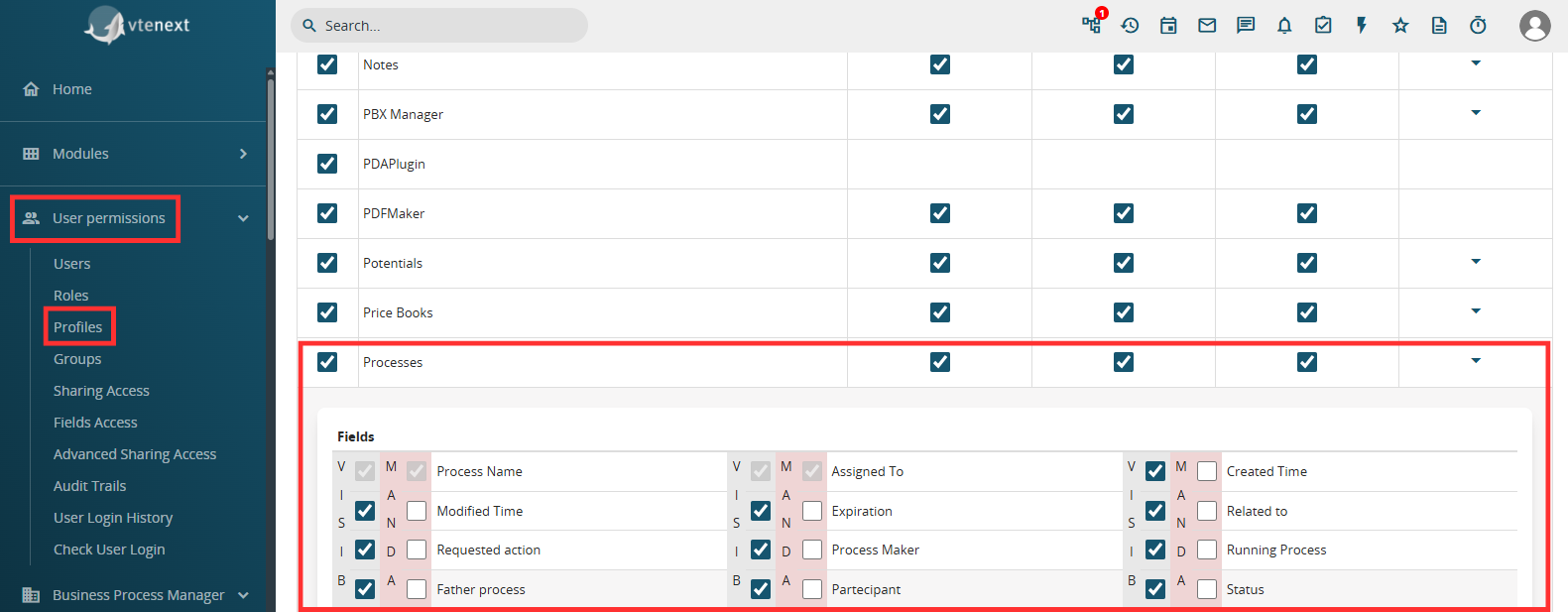
Figure 1
In order to configure a process helper, you must first configure an Action Task (create a link with a dedicated section) following the dedicated procedure (Figure 1).
NOTE: it is advisable to use the User Task symbol, as we are indicating an activity that will be charged to the user.
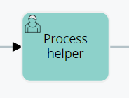
Figure 2
After the User Task, in this specific case it is essential to create a Task within which to perform some checks to allow the process to stop and present the dynamic form (Figure 2).
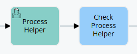
Figure 3
Once inside the User Task (in our example “Process Helper”) in configuration mode, we will find the section called “Process Helper” with all the related fields (Figure 3)

Figure 4
Once the main fields have been configured (Assigned to, Linked to, Action requested) we will create the necessary blocks and fields in the dynamic form in order to save the information that will be entered by the user (for more information on their configuration, see the chapter ...).
To better understand how it works, below is an example of a process helper aimed at requesting approval of an internal flow by filling in a single field called "Action" (Figure 4).
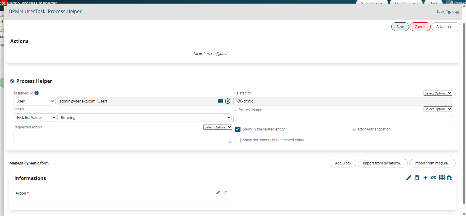
Figure 5
This is a picklist type field with the following 3 static values: “empty”, “APPROVATE” and “DO NOT APPROVE” and with mandatory permissions as Default (Figure 5)

Figure 6
In the associated Control Task (called “Process Helper Control”) a condition is indicated that allows the process not to continue with its flow until a value other than blank has been entered (which instead represents the default value of the picklist) (Figure 6)

Figure 7
The two conditions inserted in separate groups allow the flow to be routed in two different paths based on the item selected by the user.
On the operational side, the process helper presents itself with a preview mask as shown in Figure 7, this is because the “Show in the linked entity” flag has been activated.
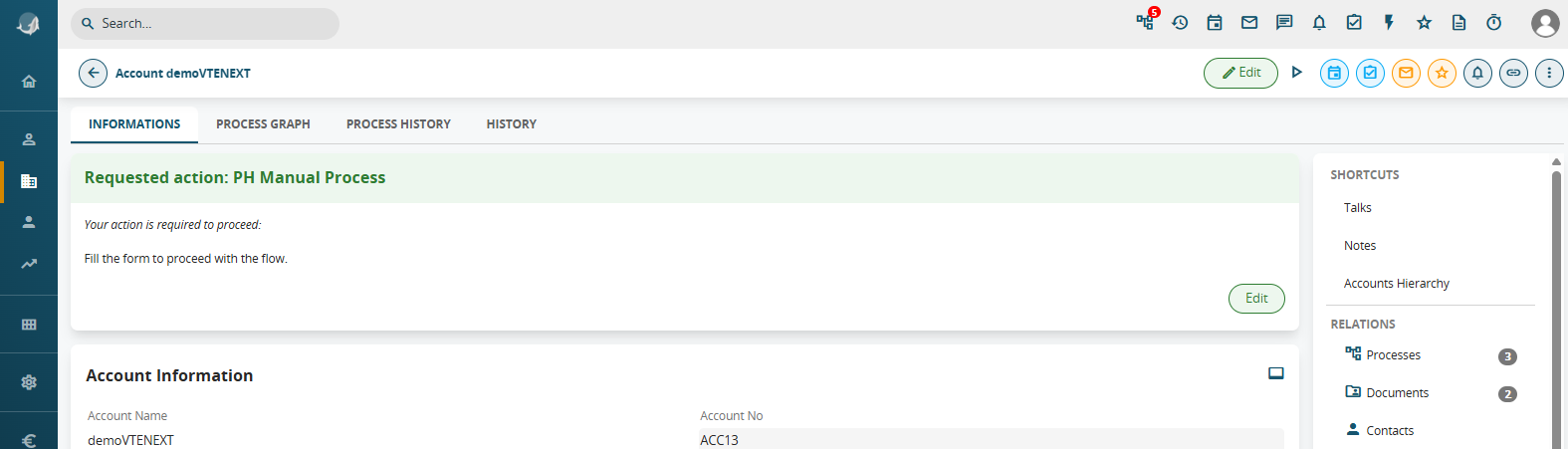
Figure 8
Clicking the Fill button displays a popup with the content of the dynamic form.
The user simply has to fill in the “Action” field and finally click on the “Save” button (Figure 8)
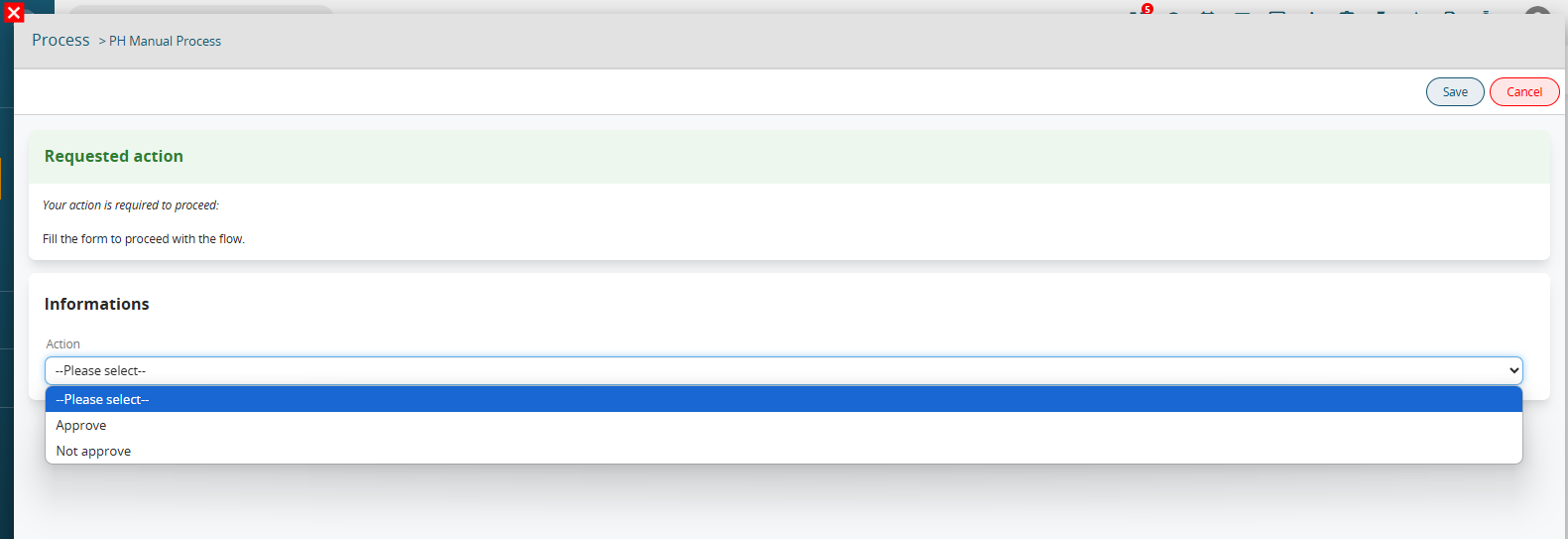
Figure 9
6.2 Example of using Process Helper to request external user data
As anticipated in the introductory chapter, one of the most common uses of the process helper concerns the creation of customized masks that can be presented to external users in order to request and save information.
The blocks and fields that make up these masks are called “dynamic forms”.
In order to configure a process helper, you must first configure an Action Task (create a link with a dedicated section) following the dedicated procedure (Figure 1).
NOTE: it is advisable to use the User Task symbol, as we are indicating an activity that will be carried out by the user.

Figure 1
After the User Task, in this specific case it is essential to create a Task within which to perform some checks to allow the process to stop and present the dynamic form (Figure 2).

Figure 2
Once inside the User Task (in our example “Process Helper”) in configuration mode, we will find the section called “Process Helper” with all the related fields (see Figure 3)
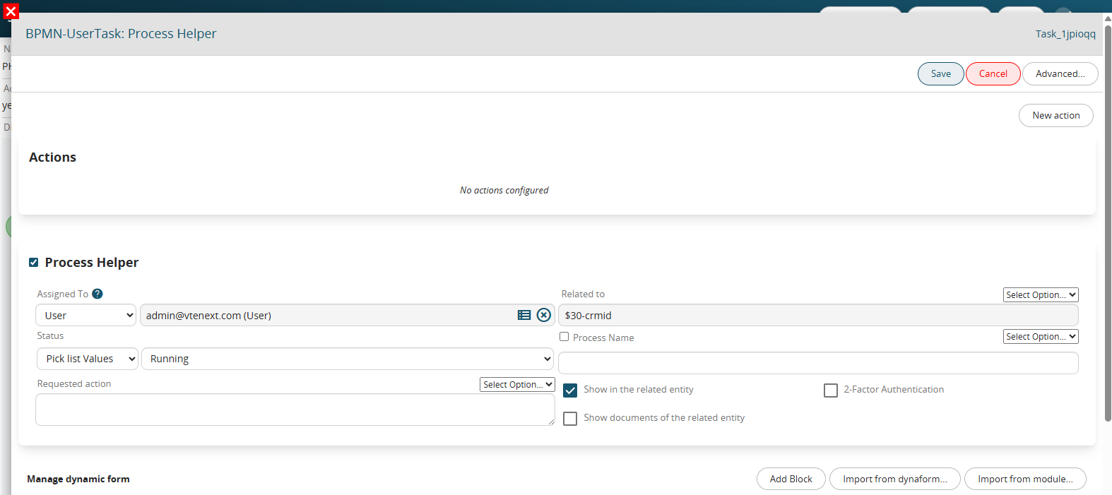
Figure 3
Once the main fields have been configured (Assigned to, Linked to, Action requested) we will create the necessary blocks and fields in the dynamic form in order to save the information that will be entered by the user.
To better understand how it works, below is an example of a process helper aimed at requesting approval of a flow step by filling in a single field called “Action” (Figure 4).
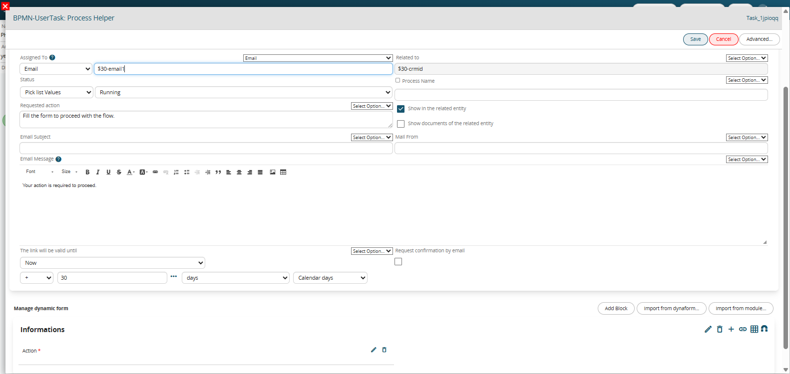
Figure 4
This is a picklist type field with the following 3 static values: “empty”, “APPROVATE” and “DO NOT APPROVE” and with mandatory permissions as Default (Figure 5)
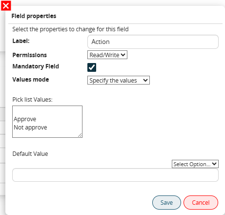
Figure 5
In the associated Control Task (called “Process Helper Control”) a condition is indicated that allows the process not to continue with its flow until a value other than blank has been entered (which instead represents the default value of the picklist) (Figure 6)

Figure 6
The two conditions inserted in separate groups allow the flow to be routed in two different paths based on the item selected by the user.
On the operational side, an email is sent to the address entered in the “Assigned to” field that has a button called “CLICK HERE” (Figure 7)

Figure 7
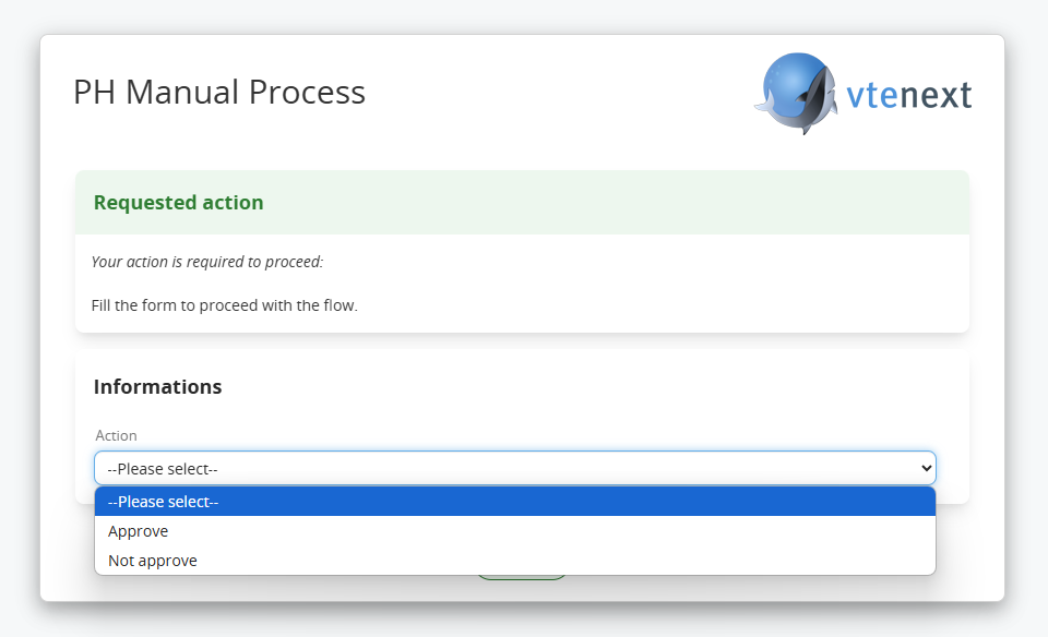
Figure 8
Once saved, a warning message will be displayed on the landing page to indicate that the operation was performed correctly (Figure 9)
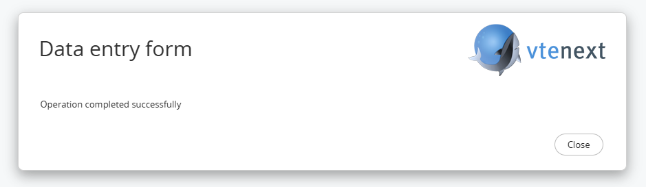
Figure 9
6.3 Example of using Process Helper to request Business Portal user data
As anticipated in the introductory chapter, one of the most common uses of the process helper concerns the creation of customized forms that can be presented to Business Portal users in order to request and save information.
For details on the conditions and requirements to be able to activate the management of processes on the Customer Portal side, we recommend consulting chapter 18.3 of the general Vtenext manual.
The blocks and fields that make up these forms are called "dynamic forms".
In order to configure a process helper, you must first configure an Action Task (create a link with a dedicated section) following the dedicated procedure (Figure 1).
NOTE: it is advisable to use the User Task symbol, as we are indicating an activity that will be charged to the user.

Figure 1
After the User Task, in this specific case it is essential to create a Task within which to perform checks to allow the process to stop and present the dynamic form (Figure 2).

Figure 2
Once inside the User Task (in our example “Process Helper”) in configuration mode, we will find the section called “Process Helper” with all the related fields (see Figure 3)

Figure 3
Once the main fields have been configured (Assigned to, Linked to, Action requested) we will create the necessary blocks and fields in the dynamic form in order to save the information that will be entered by the user.
To better understand how it works, below is an example of a process helper aimed at requesting approval of a flow step by filling in a single field called “Action” (Figure 4).
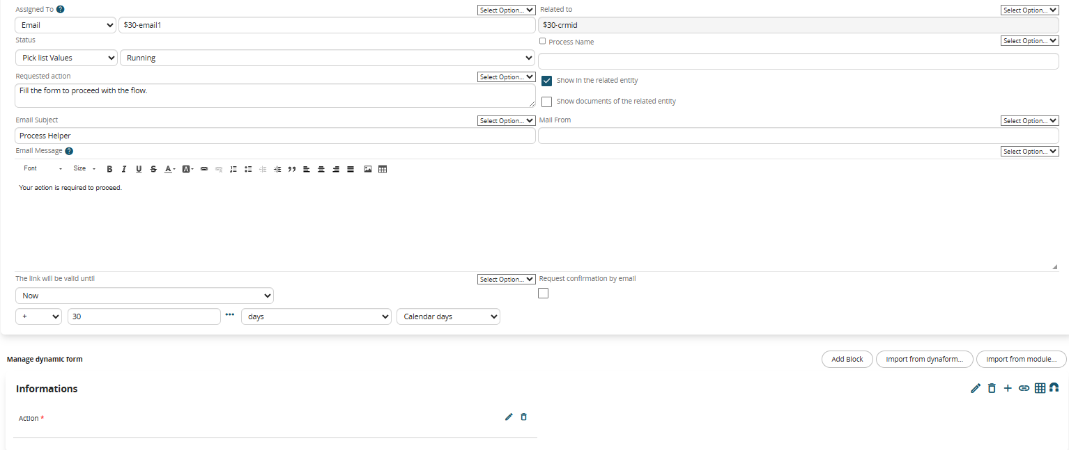
Figure 4
This is a picklist type field with the following 3 static values: “empty”, “APPROVATE” and “DO NOT APPROVE” and with mandatory permissions as Default (Figure 5)

Figure 5
In the associated Control Task (called “Process Helper Control”) a condition is indicated that allows the process not to continue with its flow until a value other than blank has been entered (which instead represents the default value of the picklist) (Figure 6)
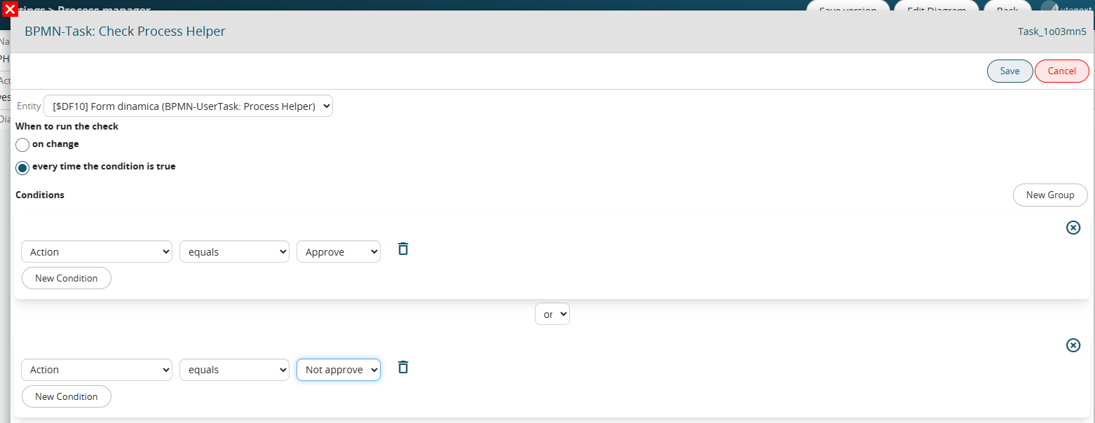
Figure 6
The two conditions inserted in separate groups allow the flow to be routed in two different paths based on the item selected by the user.
On the operational side, an email is sent to the address entered in the “Email” field of the Contact or Company entered in the “Assigned to” field of the Process helper that has a button called “CLICK HERE” (Figure 7)

Figure 7
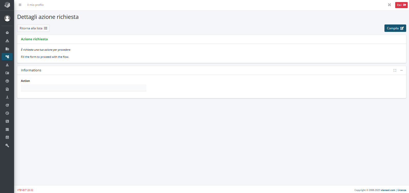
Figure 8
The user will simply have to click on the “Fill” button (Figure 9), fill in the “Action” field and finally click on the “Save” button (Figure 10)
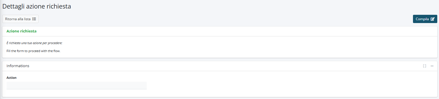
Figure 9
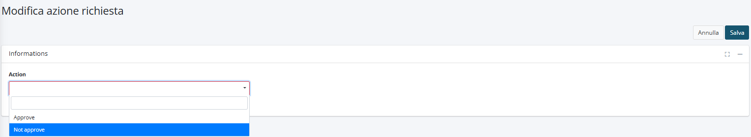 Figure 10
6.4 Example of using Process Helper to activate Process Graph
Configuring a process helper within a process allows you to activate the section called “Process Graph” available in the “PROCESS GRAPH” tab of the details of each individual record (Figure 1)
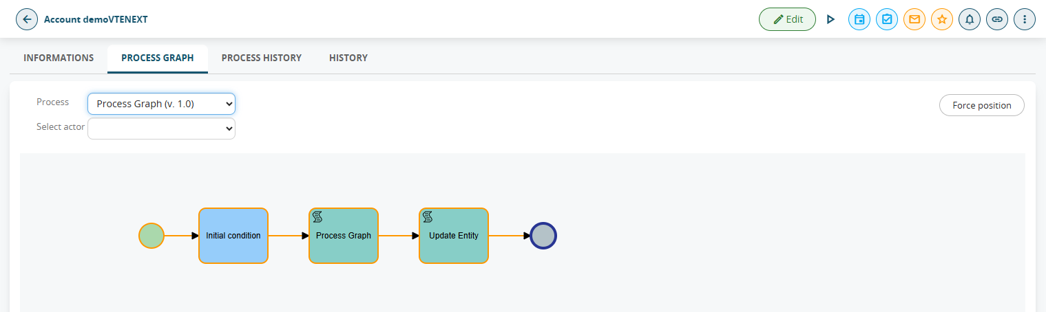
Figure 1
From this screen you can view the path taken from start to finish and the users (called “Participants”) involved in the various Tasks/Action Tasks of the process (Figure 2).
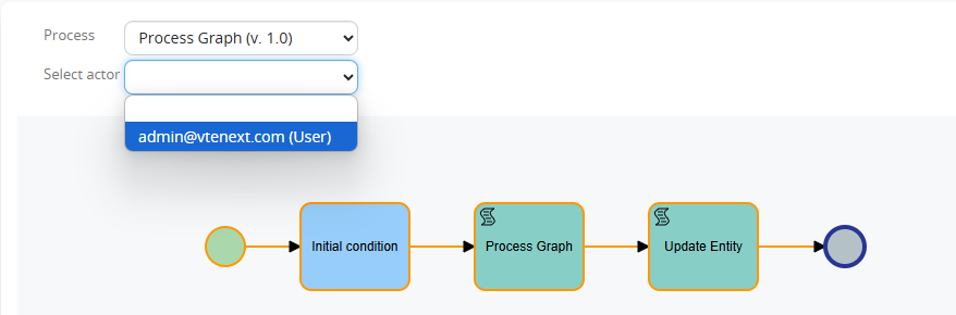
Figure 2
Also, since version 24.08, the individual Tasks/Action Tasks of the process that have already been executed are highlighted in yellow (Figure 3)
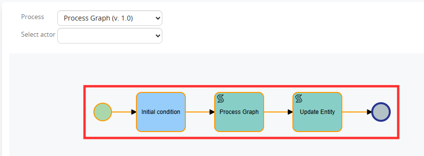
Figure 3
Instead, the point where the process is located at that specific moment is highlighted in blue (Figure 4).
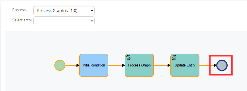
Figure 4
By clicking on each individual Task/Action Task it is possible to view the specific logs relating to those who performed the specific task and the relative time frame (Figure 5)
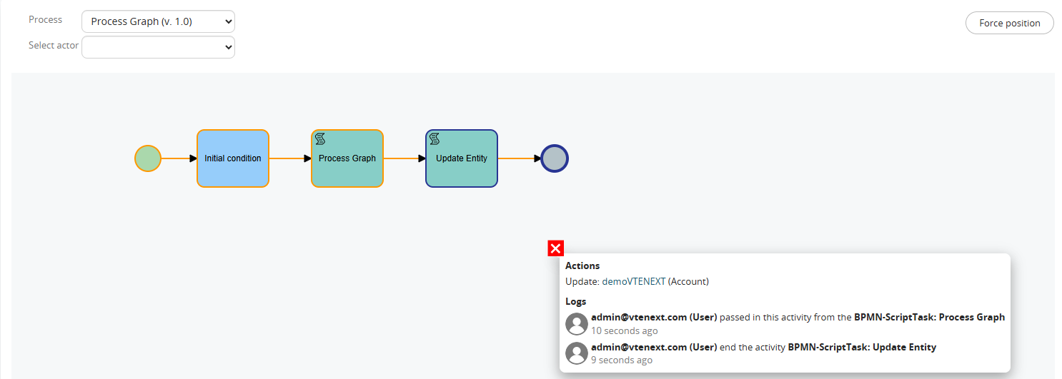
Figure 5
From version 24.08, if a dynamic Form is configured in a Process helper, clicking on the related Action Task and then on “Details” will allow you to view its content (Figure 6)
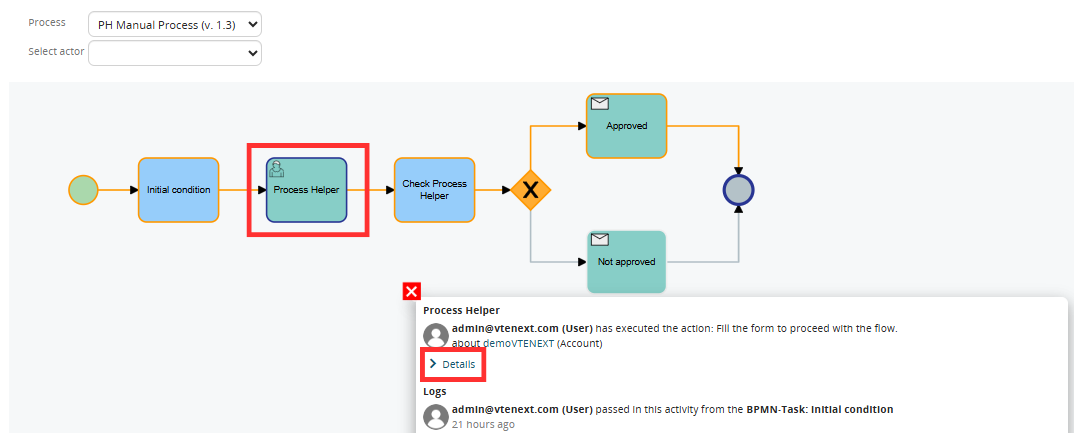
Figure 6
With a user with Administrator permissions, it is possible to perform direct maintenance on a single process instance by being able to move the point of execution of the flow forward (to avoid the execution of some Tasks/Action Tasks) or backward (to re-execute some Tasks/Action Tasks).
To proceed with these operations, you must click on “Force position” (Figure 7), then on the Task/Action Task on which you want to position the process (Figure 8), then on “OK” in the confirmation popup (Figure 9), then on “Continue execution” (Figure 10) and finally on “OK” in the confirmation popup (Figure 11).
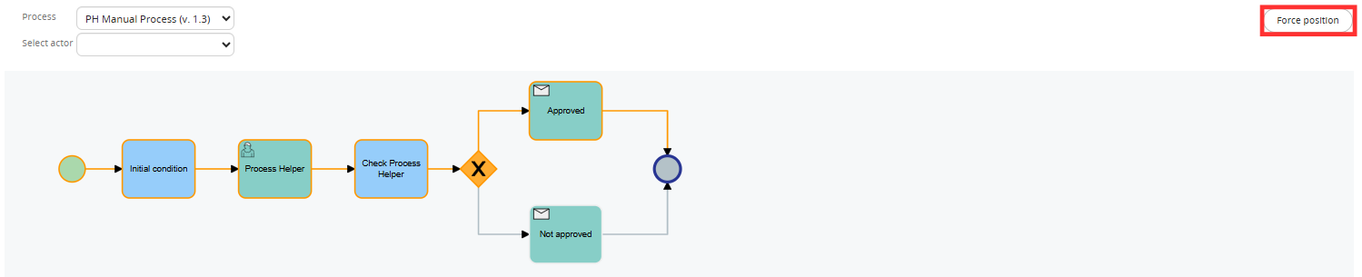
Figure 7
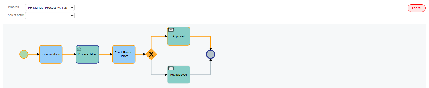
Figure 8
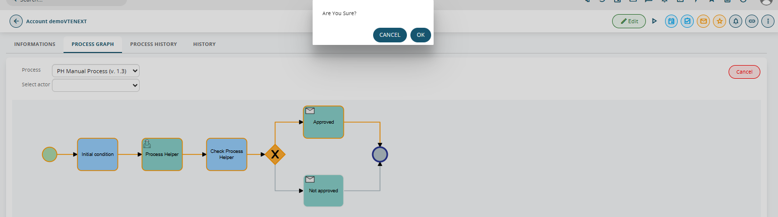
Figure 9
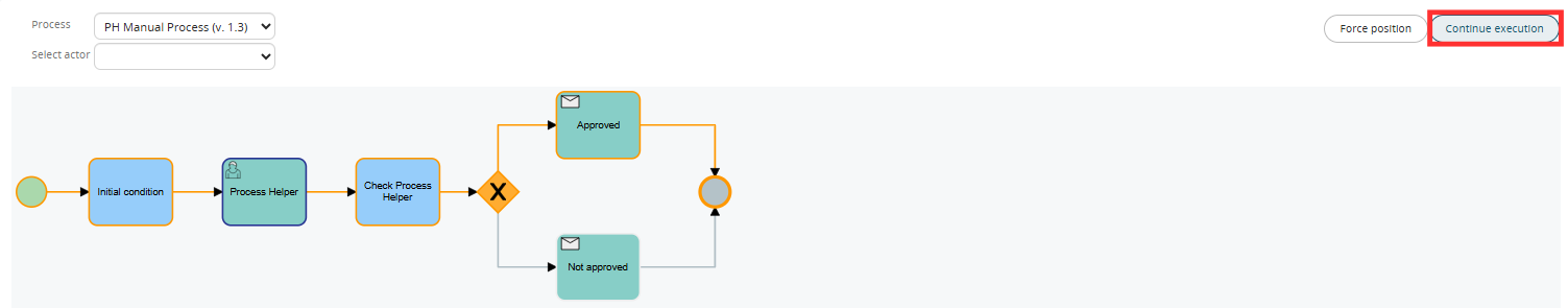
Figure 10
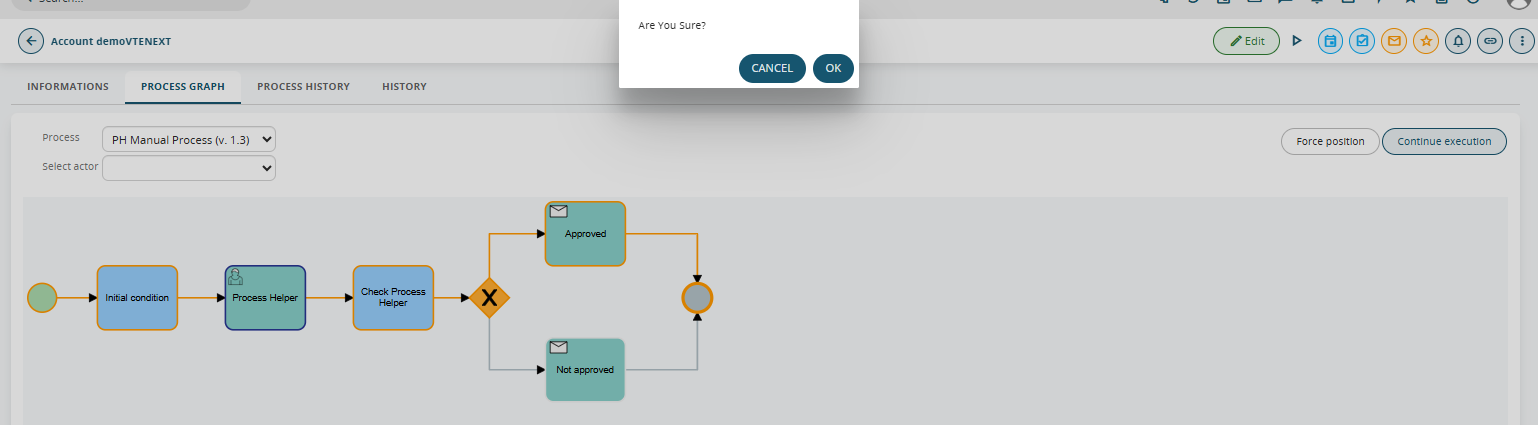
Figure 11
In the re-executed Tasks/Action Tasks it is reported whether the execution was performed through a position force or not (Figure 12)
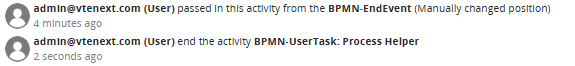
Figure 12
It is recommended to configure the aforementioned Process helper inside an Action Task inserted immediately after the Initial Condition Task to ensure that the graph is activated a few moments after the actual start of the process (Figure 13).
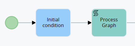
Figure 13
To activate the Process helper, simply fill in the mandatory fields, namely the “Assigned to” and “Linked to” fields (Figure 14).
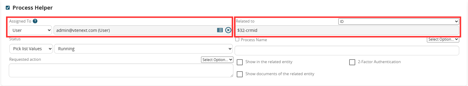
Figure 14
NOTE: to avoid encountering errors, it is recommended to insert in the Linked to field the ID of the instance of the main module involved in the process, i.e. the record on which the process was triggered, otherwise you risk inserting the ID of an instance that does not exist at that specific point in the flow.
6.5 Example of Process Helper usage for internal process use
As anticipated in the introductory chapter, one of the uses of the process helper concerns the creation of virtual spaces in which to store data or carry out operations necessary exclusively within the process (and which therefore would be useless to historicize in the CRM modules).
To proceed with the configuration of the process helper, you must first configure an Action Task (create link with dedicated section) following the dedicated procedure (Figure 1).
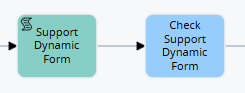
Figure 1
NOTE: It is NOT mandatory to create a subsequent Task, since the checks that would be performed within it would not be aimed at stopping the process to present the dynamic form but rather to perform a simple check on the data present in the fields of the dynamic form (which we remind you were not entered directly by any user).
Once inside the Action Task (in our example “Dynamic support form”) in configuration mode, we will find the section called “Process Helper” with all the related fields (Figure 3)
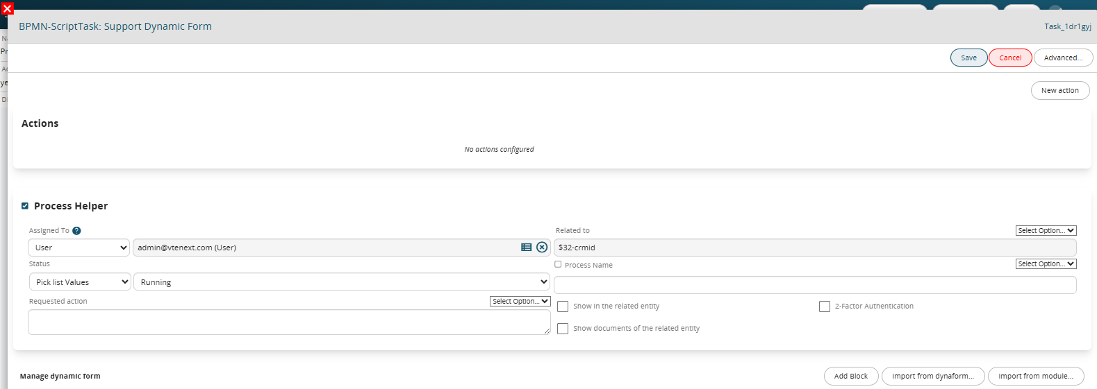
Figure 3
Once the main fields have been configured (Assigned to, Linked to, Action requested) we will create the necessary blocks and fields in the dynamic form based on the data we want to use or the calculations we want to perform.
To better understand how it works, below is an example of a process helper designed to calculate the difference in days between two dates and store the result in a field called "Calculation result", this to verify whether the two values taken into consideration are equal or different (and consequently perform different actions) (Figure 4).
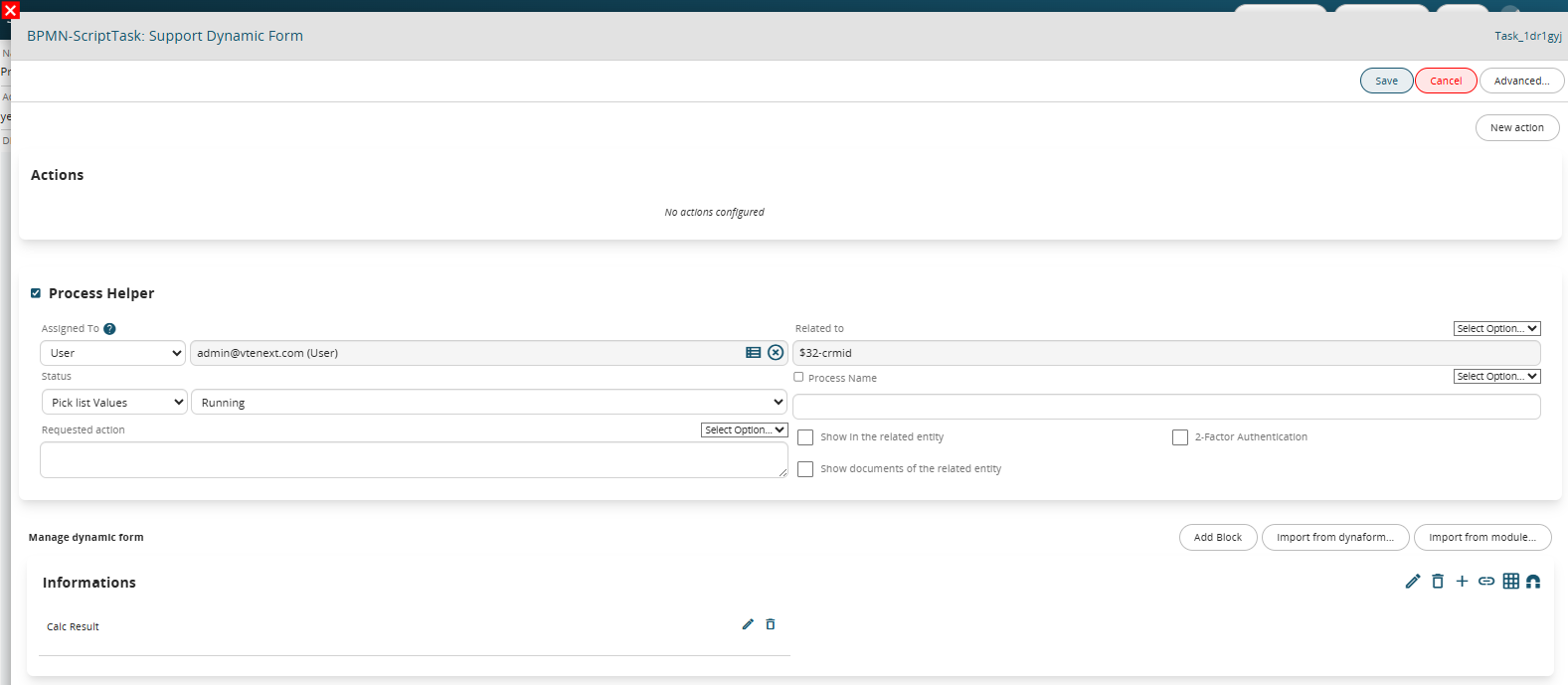
Figure 4
This is a “Number” type field in which the SDK “Diff Date” function is inserted as a Default value, which allows you to perform the difference between two dates.
NOTE: By default, the system returns the result in seconds, but if you want to obtain the result in days, you must pass the word “days” as the third parameter, as done in this example (Figure 5)
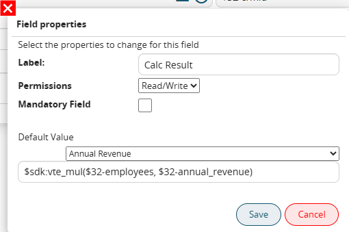
Figure 5
In the associated Control Task (called “Dynamic Support Form Control”) two different groups of conditions are indicated that allow the process to take different paths based on the calculation result (Figure 6).
Specifically, it is checked whether the content of the “Calculation Result” field is equal to or different from 0, this is because if the two compared values are equal the calculated difference will be equal to 0, otherwise it will be different from 0.
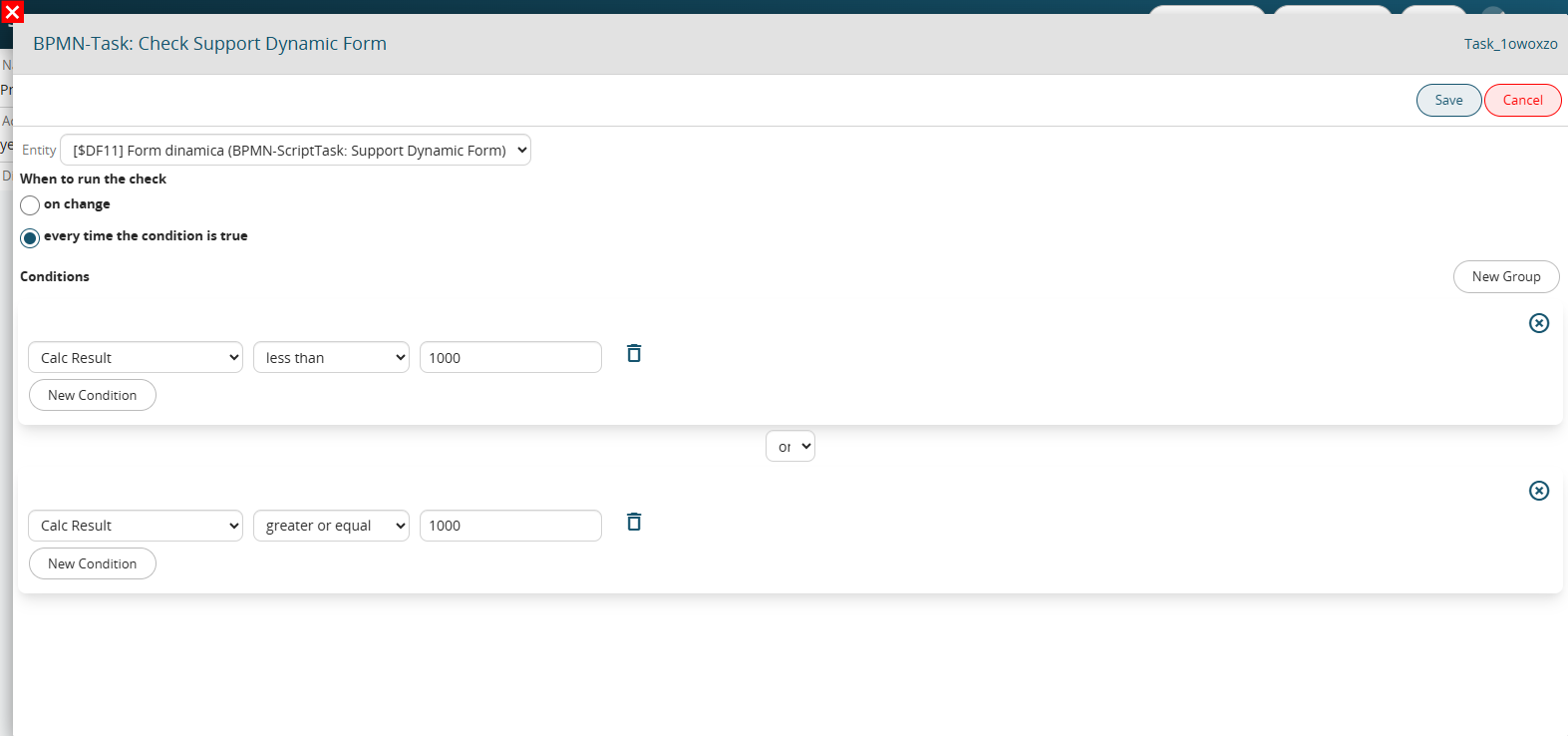
Figure 6